Posts

Showing posts from June, 2023

Die Casting

Image
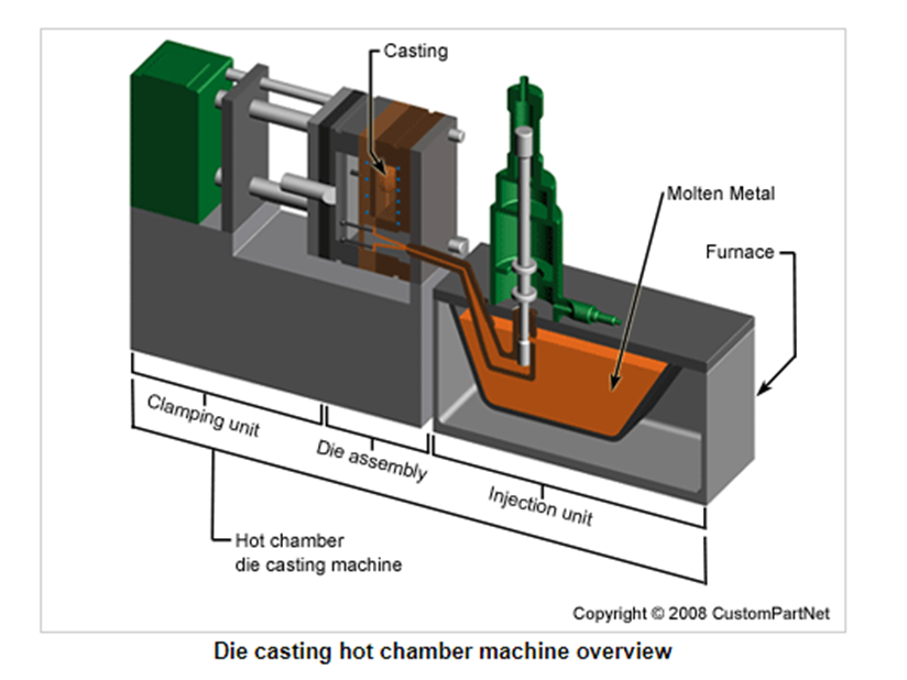
                            Die Casting   Die casting is a manufacturing process that can produce geometrically complex metal parts through the use of reusable molds, called dies. The die casting process involves the use of a furnace, metal, die casting machine, and die. The metal, typically a non-ferrous alloy such as aluminum or zinc, is melted in the furnace and then injected into the dies in the die casting machine. There are two main types of die casting machines - hot chamber machines (used for alloys with low melting temperatures, such as zinc) and cold chamber machines (used for alloys with high melting temperatures, such as aluminum). The differences between these machines will be detailed in the sections on equipment and tooling. However, in both machines, after the molten metal is injected into the dies, it rapidly cools and solidifies into the final part, called the casting. The steps in this process are described in greater detail in the next section.            

Heat Treatment

Heat Treatment • process of controlled heating and cooling of metals  • Alter their physical and mechanical properties  • without changing the product shape  • sometimes takes place inadvertently due to manufacturing processes that either heat or cool the metal such as welding or forming DEFINATION: A combination of heating & cooling operation timed & applied to a metal or alloy in the solid state in a way that will produce desired properties.- Metal Hand Book (ASM) • Often associated with increasing the strength of material • Can also be used to obtain certain manufacturing objectives like – To improve machining & formability, – To restore ductility – To recover grain size etc. – Known as Process Heat Treatment • Heat treatment done for one of the following objective:  –Hardening.  – Softening. – Property modification. Heat treatment applied materials • Hardening heat treatments particularly suitable for Steels – Many phase transformation involved even in plain carbon stee
Image
Angle Measuring Instruments There are a wide variety of geometries that are measured in angular units. These varieties include angular separation of bounding planes, digression from a basic direction, angular spacing conditions related to a circle, etc. Because of these diverse geometrical forms, different types of methods, equipment and instruments are available to measure angles in common angular units of degree, minute and second. Several factors come into the role in the selection of the appropriate angular measuring instruments. These factors may be the size, general shape of the part, the location and angular accessibility of the feature to be measured, expected range of accuracy, etc. As in linear measurement, they can be categorized into two groups. The first one is the standard line instrument. It includes divided scales like protractors, Bevel Protractors. The second category of angular measuring instruments is called face standard instruments. Sine bars and angle gauges fall

Namomaterials

 Nanomaterials can be defined as materials possessing, at minimum, one external dimension measuring 1-100nm. The definition given by the European Commission states that the particle size of at least half of the particles in the number size distribution must measure 100nm or below. Nanomaterials can occur naturally, be created as the by-products of combustion reactions, or be produced purposefully through engineering to perform a specialised function. These materials can have different physical and chemical properties to their bulk-form counterparts. What are the uses of Nanomaterials? Due to the ability to generate the materials in a particular way to play a specific role, the use of nanomaterials spans across various industries, from healthcare and cosmetics to environmental preservation and air purification. The healthcare field, for example, utilises nanomaterials in a variety of ways, with one major use being drug delivery. One example of this process is whereby nanoparticles are b
Image
  Animated Infographic of How a Car Engine Works The animated infographic of how a four-stroke  Otto-cycle  engine works. This animation was made by  Jacob Neal  and does a nice job of giving the basics of How a Car Engine Works with pictures in motion.
Image
  23 Different Types of Hammers A Hammer is a mechanical tool that delivers a sudden impact to an object. Commonly hammers are used to drive nails, fit parts, forge metal and break apart objects. There are different types of hammers in use, they vary in shape, size and structure. Here 23 different types of hammers pictures are shown below. Brick Hammer The chisel side scores a line around a brick. The brick hammer can break the brick in two parts. Traditional curved-claw Hammer Traditional curved-claw Hammer drives nails well and removes nails easily with the rocking action of its curved claw.   Body mechanic’s Hammer Body mechanic’s hammer is used along with a small curved anvil called a dolly to remove dents from car panels.   Lineman’s Hammer Lineman’s hammer is best suited to driving big lag screws and hammering bolts in utility-pole work.   Chasing Hammer Chasing hammers are designed and shape metal jewelry.   Titanium framing Hammer Titanium framing hammer has a titanium body wit
Image
  Welding Symbols According to IS: 813 – 1991 Basic Weld Symbols The basic weld symbols according to IS: 813 – 1961 (reaffirmed 1991) are shown below with sectional representation and symbol in the tabular form for different forms of weld. Fillet, square butt, single-V butt, double-V butt, single-U butt, double-U butt, single bevel butt, double bevel butt, single bevel butt, double bevel butt, Single-J butt, Bead, Stud, sealing run, spot, seam, mashed seam, plug, backing strip,  stitch, projection, flash, butt resistance or pressure are the different form of welds. Supplementary Weld Symbols: In addition to the above basic weld symbols, some supplementary symbols according to IS: 813 – 1961 (reaffirmed 1991) are shown below with drawing representation and symbol in the tabular form. Weld all round, field weld, flush contour, convex contour, concave contour, grinding finish, machining finish and chipping finish are the different particulars of supplementary weld symbols. Elements of a W
Image
  Commonly Used Tools in Foundry Shop A foundry shop is a place where the metal  casting  is prepared by melting and pouring the molten metal into moulds. Some of the commonly used tools in the foundry shop for the molding process are  shovel ,  trowel ,  riddle ,  rammer ,  draw spike ,  swab ,  vent wire  and  slick tool . Shovel: Shovel tool is used for mixing and tempering molding sand and for moving the sand pile to the flask. Trowel: A trowel tool is used to shape and smooth the surfaces of the mold and for doing small repairs. They are made of steel and are relatively long and narrow. Riddle: A Riddle tool is a screen or sieve used to remove small pieces of metal and foreign particles from the molding sand. Rammer: Rammer tool is used to compress the molding sand. The hand rammer is made of tool and resembles a handless mallet with one end flat and the other end blunt edge. Draw spike: Draw spike tool is used to remove the pattern from the mold and also used for rapping the patt