Autocollimator
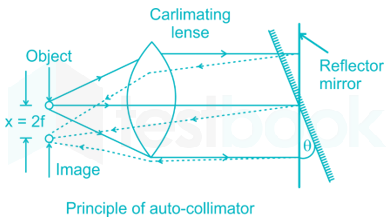
An autocollimator is an optical instrument for non-contact measurement of angles. They are typically used to align components and measure deflections in optical or mechanical systems. An autocollimator works by projecting an image onto a target mirror and measuring the deflection of the returned image against a scale, either visually or by means of an electronic detector. A visual autocollimator can measure angles as small as 1 arcsecond (4.85 microradians), while an electronic autocollimator can have up to 100 times more resolution.
Visual autocollimators are often used for aligning laser rod ends and checking the face parallelism of optical windows and wedges. Electronic and digital autocollimators are used as angle measurement standards, for monitoring angular movement over long periods of time and for checking angular position repeatability in mechanical systems. Servo autocollimators are specialized compact forms of electronic autocollimators that are used in high-speed servo-feedback loops for stable-platform applications. An electronic autocollimator is typically calibrated to read the actual mirror angle.
Angle dekkor
ANGLE DEKKOR
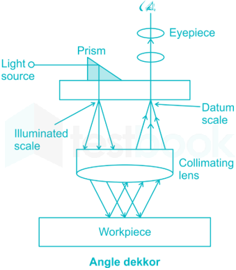
This is also a type of auto-collimator. There is an illuminated scale in the focal plane of the collimating lens. This illuminated scale is projected as a parallel beam by the collimating lens which after striking a reflector below the instrument is refocused by the lens in the filed of view of the eyepiece. In the field of view of microscope, there is another datum scale fixed across the center of screen. The reflected image of the illuminated scale is received at right angle to the fixed scale as shown in fig. Thus the changes in angular position of the reflector in two planes are indicated by changes in the point of intersection of the two scales. One division on the scale is calibrated to read 1 minute.
Uses of Angle Dekkor
(i) Measuring angle of a component
Angle dekkor is capable of measuring small variations in angular setting i.e. determining angular tilt. Angle dekkor is used in combination with angle gauge. First the angle gauge combination is set up to the nearest known angle of the component. Now the angle dekkor is set to zero reading on the illuminated scale. The angle gauge build up is then removed and replaced by the component under test. Usually a straight edge being used to ensure that there is no change in lateral positions. The new position of the reflected scale with respect to the fixed scale gives the angular tilt of the component from the set angle.
(ii) Checking the slope angle of a V-block
Figure shows the set up for checking the sloping angle of V block. Initially, a polished reflector or slip gauge is attached in close contact with the work surface. By using angle gauge zero reading is obtained in the angle dekkor. Then the angle may be calculated by comparing the reading obtained from the angle dekkor and angle gauge.
(iii) To measure the angle of cone or Taper gauge
Initially, the angle dekkor is set for the nominal angle of cone by using angle gauge or sine bar. The cone is then placed in position with its base resting on the surface plate. A slip gauge or reflector is attached on the cone since no reflection can be obtained from the curved surface. Any deviation from the set angle will be noted by the angle dekkor in the eyepiece and indicated by the shifting of the image of illuminated scale.


Comments